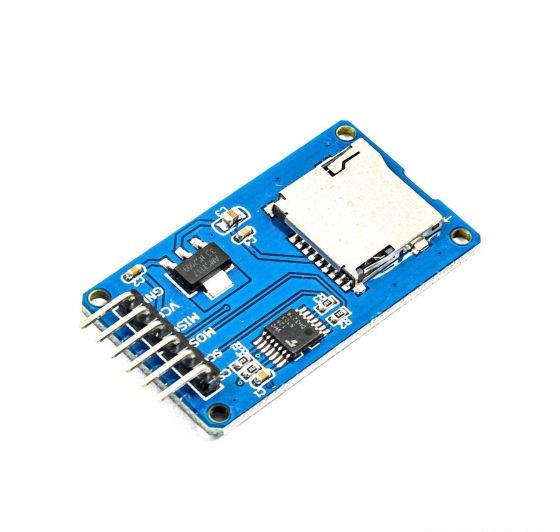
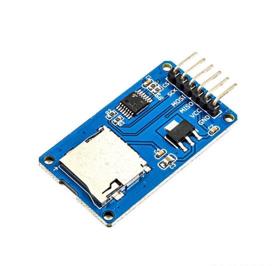
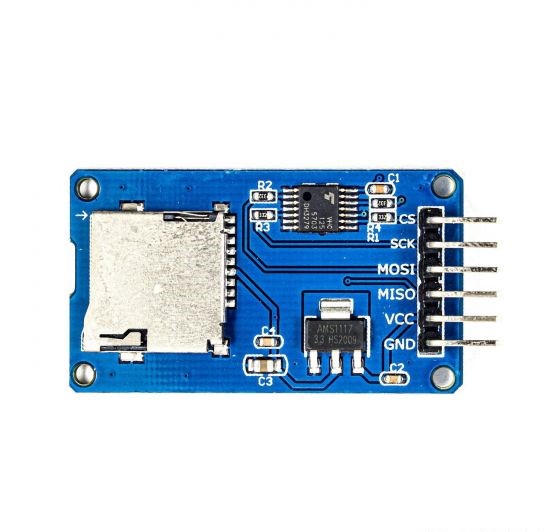
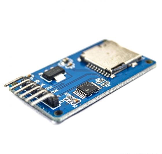
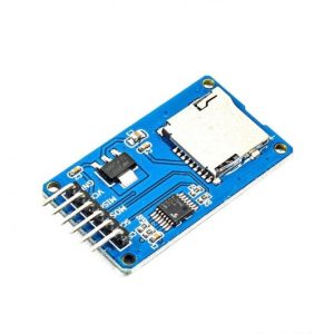
The micro SD card module contains two main components that make it undoubtedly easy to add data logging the Arduino project.
The operating voltage of any standard micro SD Cards is 3.3 V. So we cannot directly connect it to circuits that use 5V logic. In fact, any voltages exceeding 3.6V will permanently damage the micro SD card.
That’s why; the module has an onboard ultra-low dropout regulator that will convert voltages from 3.3V – 6V down to ~3.3V.
Before you insert the micro SD card into the module and hook it up to the Arduino, you must properly format the card. For the Arduino library, we’ll be discussing, and nearly every other SD library, the card must be formatted FAT16 or FAT32. If you have a new SD card, chances are it’s already pre-formatted with a FAT file system.
Note that each Arduino Board has different SPI pins which should be connected accordingly. For Arduino boards such as the UNO/Nano those pins are digital 13 (SCK), 12 (MISO) and 11 (MOSI).
You will also need a fourth pin for the ‘chip/slave select’ (SS) line. Usually, this is pin 10 but you can actually use any pin you like.
If you have a Mega, the pins are different! You’ll want to use digital 50 (MISO), 51 (MOSI), 52 (SCK), and 53 (SS).
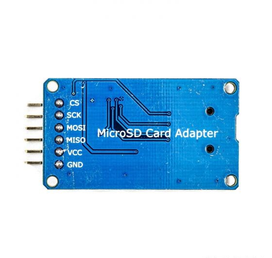
Pinout:
GND ground
VCC power supply
MISO SPI bus
MOSI SPI bus
SCK SPI bus
CS Chip select signal pin
3.3V voltage regulator circuit:
LDO regulator output is 3.3V level converter chip, Micro SD card supply;
Level conversion circuit:
Micro SD card into the direction of the signal is converted to 3.3V, MicroSD card interfaces to control the direction of the MISO signal is also converted into 3.3V, general AVR microcontroller system can read the signal;
Micro SD card connector:
a self-bomb deck, easy card insertion.
Positioning holes:
4 M2 screws positioning hole diameter is 2.2mm, the positioning of the module is easy to install, to achieve inter-module combination;


Reviews
There are no reviews yet.